
| Content follows this message If you have enjoyed my articles, please consider these charities for donation: |
A UART Implementation in VHDL
I’m still working on my Soft-CPU TPU, but wanted to implement a communications channel for it to use in order to get some form of input and output from it. The easiest way to do this is to use a UART, and connect it to a USB to Serial converter for logic-level asynchronous communications.
Knowing that I’m still pretty new to VHDL and working with FPGA systems in general at this level, I decided to develop my own UART implementation. Some may roll their eyes at this, knowing there are plenty out there, and even constructs to utilize real hardware on the Spartan 6 FPGA I’m using; but I’m a fan of learning by doing.
Serial Communications
What I’m implementing is a transmitter and receiver which can operate at any baud rate, with 8 data bits, no parity and 1 stop bit. It should be able to communicate over a COM post to a PC, or to another UART. It’s working at Logic-Level voltages, which is very important – you need to use a logic level USB-Serial cable for this. Using an RS232 serial will damage things if it uses the higher voltages specified.
Looking at how we transmit, the waveform looks as follows:
 Assuming that the ‘baud’ clock is running at the correct frequency we require, you can see that it’s fairly simple how all of this works. The idle state for the TX line is always logic high. This may seem weird, but historically the distances the wires crossed meant they were susceptible to damage, and having the idle state high meant if any problem occurred with the physical wires, you’d know about it very quickly.
To transmit an 8-bit byte, a start bit is emitted which is logic low. One ‘baud tick’ later, the least significant bit of the byte is sent, and then every baud tick follows the next bit until the most significant bit is sent. Finally, a stop bit is sent, which is logic high. At this point another byte can be sent immediately – or the line left idle to transmit later, after a delay.
Transmitter States
The transmitter is very simple. There is a data byte input, and a txSig port which is used to signal that the bits on the data output should be sent. When txSig is asserted, state moves from idle to a start state where a start bit is issued. From there, we progress to the data state, where the 8 bits of data are pushed least-significant-bit to output. Finally there is the stop bit state, before moving back to idle, or straight back to start in the case data is being streamed out.
 For the states, I use an integer signal as it seemed the simplest and generally the most obvious way to go about it. The whole transmitter code is below.
tx_proc: process (tx_clk, I_reset, I_txSig, tx_state)
begin
  -- TX runs off the TX baud clock
  if rising_edge(tx_clk) then
    if I_reset = '1' then
      tx_state <= 0;
      tx_data <= X"00";
      tx_rdy <= '1';
      tx <= '1';
    else
      if tx_state = 0 and I_txSig = '1' then
        tx_state <= 1;
        tx_data <= I_txData;
        tx_rdy <= '0';
        tx <= '0'; -- start bit
      elsif tx_state < 9 and tx_rdy = '0' then
        tx <= tx_data(0);
        tx_data <= '0' & tx_data (7 downto 1);
        tx_state <= tx_state + 1;
      elsif tx_state = 9 and tx_rdy = '0' then
        tx <= '1'; -- stop bit
        tx_rdy <= '1';
        tx_state <= 0;
      end if;
    end if;
  end if;
end process;
As you can see from the VHDL, the start state is tx_state=0, the data state is tx_state=1..8 and the stop state is tx_state=9. The process is idle when tx_state is 0 with I_txSig=0. The tx_clk baud clock is generated from the higher-frequency system clock using a counter:
-- TX standard baud clock, no reset
  if tx_clk_counter = 0 then
    -- chop off LSB to get a clock
    tx_clk_counter <= to_integer(unsigned(I_clk_baud_count(15 downto 1)));
    tx_clk <= not tx_clk;
  else
    tx_clk_counter <= tx_clk_counter - 1;
  end if;
The way the I_clk_baud_count value is set is as follows:
I_clk in Hz / expected baud = I_clk_baud_count
So, for 9600bps on a system using a 50MHz clock, one would assign 50000000/9600, or 5208, to I_clk_baud_count. The TX clock is generated by negating the clock signal every 5208/2 counts of the system clock.
Testing the transmitter
Testing this is fairly simple. Auto-generating a test bench, all we need to do is put data on the in port, and then toggle the txSig signal input.
-- send hello\n - 0x48, 0x45, 0x4c, 0x4c, 0x4f, 0x0d
-- H
I_txData <= X"48";
I_txSig <= '1';
wait until O_txRdy= '0';
I_txSig <= '0';

 -- E
wait until O_txRdy= '1';
I_txData <= X"45";
I_txSig <= '1';
wait until O_txRdy= '0';
I_txSig <= '0';

...snip...
The simulation waveform results in correct TX output, which is great. I wrote up a top-level vhdl module and flashed the MiniSparan6+ board with the same style of test (obviously not using waits – it just endlessly looped over an array containing ‘hello’) and connecting to the FPGA via putty showed the TX did indeed work for this case. Time to implement receive!
Receiver
Receiving needs to be implemented differently from transmit. That statement is obvious, but it’s all about how the timing is managed and where the serial input is sampled.
If we use our existing example of how we generated the TX output, and use those methods for RX, the below waveform will be the ideal situation.
 Sampling on the rising edge of baud_clk we can see the sampled data is correct; a start bit, 8 did bits, and the stop bit (named ‘e’ just to differentiate). However, we do not control the timing of the RX input. It can be out of phase with the clock, and once it’s out of phase significantly the samples can result in incorrect data, as shown below. Additionally, there is a percentage error allowed in serial communications, and as this error accumulates it can confuse the receiver.
 We need to use a higher-rate clock, as to lower the accumulated error across a received frame.
Super-sampling (or not)
Generally when working with other UART RX hardware you’ll see mention of a clock at higher than the baud rate. This is due to the internals super-sampling the RX input and then trying to get the ideal sample area, right in the middle of the transmitted bit. For my implementation I cheated, and still only sample once per bit, but I use a 16x baud tick along with a counter for working out where the next bit is likely to be.
The falling edge of the start bit is always sampled at the system clock, in my case, 50MHz. When found, the 16x baud counter is reset, which re-aligns the baud ticks with the start bit. A counter is reset too; as there are 16 baud ticks per bit when receiving, I then sample the start bit when the counter reaches 7, move to the next state, and reset. It will then sample for data bit 0 when the counter reaches 16, and so on, until we have a whole byte of data and an end bit.
 You can see the 16 baud ticks per transmitted bit in the simulator:
 And, even see the ticks reset to re-align them with the RX when the start bit is sampled:
 The RX Code
The RX clock is based off two things, the main system clock, and then a counter which generates a ‘tick’ every 16x baud clock (the one TX uses). To generate the ticks, we use the code below.
-- RX baud 'ticks' generated for sampling, with reset
if rx_clk_counter = 0 then
  -- x16 sampled - so chop off 4 LSB
  rx_clk_counter <= to_integer(unsigned(I_clk_baud_count(15 downto 4)));
  rx_clk_baud_tick <= '1';
else
  if rx_clk_reset = '1' then
    rx_clk_counter <= to_integer(unsigned(I_clk_baud_count(15 downto 4)));
  else
    rx_clk_counter <= rx_clk_counter - 1;
  end if;
  rx_clk_baud_tick <= '0';
end if;
There are a few things that could probably be optimized here, but I kept it simple for readability reasons. Note that the RX counter generating the baud ticks has a reset, unlike the transmit clock.
The actual code for the RX is presented below, with the reset, and initial start bit detection.
rx_proc: process (I_clk, I_reset, I_rx, I_rxCont)
begin
  -- RX runs off the system clock, and operates on baud 'ticks'
  if rising_edge(I_clk) then
    if rx_clk_reset = '1' then
      rx_clk_reset <= '0';
    end if;
    if I_reset = '1' then
      rx_state <= 0;
      rx_sig <= '0';
      rx_sample_count <= 0;
      rx_sample_offset <= OFFSET_START_BIT;
      rx_data <= X"00";
      O_rxData <= X"00";
    elsif I_rx = '0' and rx_state = 0 and I_rxCont = '1' then
      -- first encounter of falling edge start
      rx_state <= 1; -- start bit sample stage
      rx_sample_offset <= OFFSET_START_BIT;
      rx_sample_count <= 0;

      -- need to reset the baud tick clock to line up with the start
      -- bit leading edge.
      rx_clk_reset <= '1';
Skipping the clock reset, which needs to be in this process (this process writes that signal, the other clock-generating process reads it) we have the initial state for the receiver, rx_state=0. This is the initial detection of the start bit, which is rx=’0′, and sampled every system clock cycle (50MHz). Once we find these, and the rxCont input is active (which is basically RX enable) we move to state 1 and set the sample offset to OFFSET_START_BIT, which I can assure you is 7!
elsif rx_clk_baud_tick = '1' and I_rx = '0' and rx_state = 1 then
      -- inc sample count
      rx_sample_count <= rx_sample_count + 1;
      if rx_sample_count = rx_sample_offset then
        -- start bit sampled, time to enable data
        -- this should check RX here. if it =1, should revert to state 0
        rx_sig <= '0';
        rx_state <= 2;
        rx_data <= X"00";
        rx_sample_offset <= OFFSET_DATA_BITS;
        rx_sample_count <= 0;
      end if;
    elsif rx_clk_baud_tick = '1' and rx_state >= 2  and rx_state < 10 then
      -- sampling data
      if rx_sample_count = rx_sample_offset then
        rx_data(6 downto 0) <= rx_data(7 downto 1);
        rx_data(7) <= I_rx;
        rx_sample_count <= 0;
        rx_state <= rx_state + 1;
      else
        rx_sample_count <= rx_sample_count + 1;
      end if;
    elsif rx_clk_baud_tick = '1' and rx_state = 10 then
      if rx_sample_count = OFFSET_STOP_BIT then
        rx_state <= 0;
        rx_sig <= '1';
        O_rxData <= rx_data; -- latch data out

        if I_rx = '1' then
          -- stop bit correct
          rx_frameError <= '0';
        else
          -- stop bit is always high, if we don't see it, there
          -- has been an issue. Signal an error.
          rx_frameError <= '1';
        end if;
      else
        rx_sample_count <= rx_sample_count + 1;
      end if;
    end if;
  end if;
end process;
The second half simply moves across all the states, sampling the start bit when our sample count gets to the offset required (for the start bit, 7). It then moves state to sampling the 8 data bits, with offsets of 16 a time, before checking the stop bit and indicating whether a frame error has occurred (the stop bit should be ‘1’).
Note that there is no real error checking, or input validation here. Technically, if rx_state=1 and our RX input is high, we should reset the RX system and go back to state 0 – as it was most likely a blip on the input, and not a real serial frame of data. I’ll probably add that later.
Other modules using this RX will use the O_rxSig output to indicate data received, and grab a new byte from the data output port. It stays high until a new frame begins receiving.
Testing the Receiver
Like the testing for transmit, I created a standard test bench, and filled it out with the usual content. For RX, I created a second clock with the same time period as the baud clock the UART is configured to use. I then have an array of the serial bitstream, and each rising edge of that clock I push the next bit across. You can see the whole test on github. Running it in the simulator, it works:
 I also created a loopback test, which uses the transmitter test bench in two speeds, feeding the TX line into the RX to ensure the data is correct. I’ve got the waveform from a run of that test below, also zoomed into the area where 115200bps is active (at the start).
 Running On Hardware
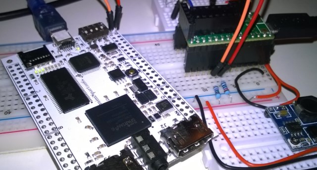
Running on hardware is easy, just assign the RX and TX ports/nets to external pins. I created a loopback top-level module so I can type into a Putty serial session and see what I type echo back.
The loopback module for the hardware uses another state machine depending on the various UART module signals. The process is fairly simple, and will just push any input from the RX to the TX and set relevant states at the correct times.
loopback: process(I_clk_50mhz, O_rxSig)
begin
if rising_edge(I_clk_50mhz) then
if O_rxSig = '1' and last_msg_valid ='0' and new_message = '1' then
last_msg <= O_rxData;
last_msg_valid <= '1';
new_message <= '0';
elsif O_txRdy = '1' and I_txSig = '0' and last_msg_valid = '1' then
I_txData <= last_msg;
I_txSig <= '1';
elsif I_txSig = '1' and O_txRdy = '0' and last_msg_valid = '1' then
I_txSig <= '0';
last_msg_valid <= '0';
elsif O_rxSig = '0' then
new_message <= '1';
end if;
end if;
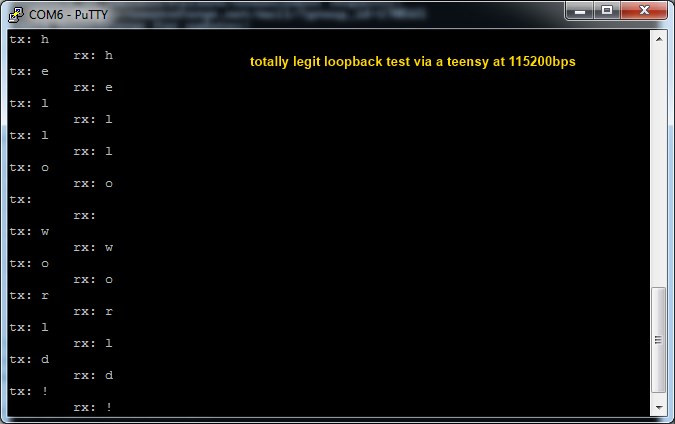
end process; Sadly, I could not find my USB to Serial TTL converter in my lab mess. It’s in there somewhere. But I did find an old Teensy 3.1 (it’s actually from my TeensyZ80 build) which I used to forward serial to and from the miniSpartan6+. Keys I typed were echoed back, at 115200bps. So a successful test.
 Wrap Up
That pretty much finishes this post off. It’s by no means a finished implementation but works for what I need. I’ll be using it with TPU as a peripheral, and memory mapping the various ports as to control it from software. I think I’ll add some FIFO buffers to the input and output data lines to ensure I don’t loose data, implement the RX error checking I mentioned earlier, and also add a ‘number of frames’ counter for software-side error checking.
It should be made clear though, that there are probably UART constructs available within any recent FPGA what will take up much less resources than this, and they should be used in final projects where possible and sensible!
Thanks for reading, the code for this is available on github.