
| Content follows this message If you have enjoyed my articles, please consider these charities for donation: |
Designing a CPU in VHDL, Part 12: Text mode video output
This is part of a series of posts detailing the steps and learning undertaken to design and implement a CPU in VHDL. Previous parts are available here, and I’d recommend they are read before continuing.
Whilst having a pixel-based video output on TPU is great, there is fundamental limitations with regard to resolutions and memory. It’s very hard to convey real information with such a resolution, and really what I need is the old style text modes of past. Think 80×25 characters, DOS/BIOS post screens. What is needed to implement that sort of output?
First of all, we need to fix down on our ‘text resolutions’. That is, the number of columns/rows, and the size in pixels of the glyphs we will draw. For this, I’m going to continue with 80 columns by 25 rows. This means, if our glyphs are 8×16 pixels, a screen resolution of 640×400 is needed. That fits nicely into 640×480, if you don’t mind a border on the bottom edge – 640x400x70Hz is an option too.
In addition to this, I want to be able to set colours for the text – foreground and background. I’d also want to make blinking of specific characters possible.
Text RAM
The areas of memory where the ASCII characters to render are stored is called TRAM in my design, standing for text ram (not to be confused with the .text executable sections in binaries!). For each character tile on our 80×25 character grid, we will have two bytes – the ASCII character, along with an attribute byte. This attribute byte will define the foreground and background colours for this glyph tile – along with whether or not the tile should be blinking.
80×25 2-byte characters comes out as 4,000 bytes. That will nearly fill two 2KB Xilinx block rams. I could have used 80×30, perfectly filling the whole 640×480 screen resolution, but I couldn’t bring myself to add that third block ram. Despite that, we do have plenty of them available on the miniSpartan6+ board. My LX25 variant has 52 available, for a total of 104KB storage. These block rams are integrated into my top-level TPU design in the same way as the existing VRAM, so they are both readable and writable by TPU, and readable (at a differing clock rate) for use by our new VHDL module which will generate the pixel stream required to represent our text characters.
Font RAM
The glyphs themselves are stored as 16 bytes, with 1 bit corresponding to a pixel in the output. A 1 value indicates foreground shading, whilst 0 is unsurprisingly background.
 With the glyphs organized linearly as a packed array of 16-byte elements, for the full 256 range of characters, we’ll need exactly two 2KB block rams. This storage could also be implemented as a ROM, but I’m going to go ahead and use the same module I use or the text ram (and VRAM) so that the user can edit the storage to implement custom glyphs.
The character generator – text_gen
In the last part, I introduced a VGA signal generator. This module takes a pixel clock, and generates sync, blanking and an x and y coordinate for the pixel that is being output. This X and Y information is used to generate a memory address, at which VRAM contains the 16-bit 565 colour to output for that pixel. The RGB value then goes to encoders, and serialized out as DVI-D.
With this signal generator, we will first change the timings to output a 640x480x60Hz set of signals. The x and Y output will no longer form an address into vram, but will be passed into a text_gen module. This new module, for a given X and Y, will generate addresses into the text and font rams, manage the operation of the data from those rams, and eventually output a pixel value. This text_gen module needs to operate at a faster clock, as for any pixel, there could be two dependent memory reads issued which need serviced before output is provided.
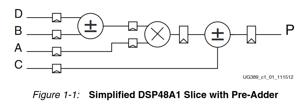
For each pixel value, the 8×16 text ’tile’ index is calculated. From this, the location in tram is known – a basic tile_y*80+tile_x calculation. In the VHDL, we use the unsigned type which has the multiplication operation defined.
tram_addr_us <= (unsigned( I_y(11 downto 4)) * 80) + unsigned(I_x(11 downto 3));This synthesizes to a [DSP48A1][5]. There are timing considerations here that I need to take into account – more on that later.
 The 16-bit data word from TRAM is captured after several cycles of latency. This data is latched within text_gen, and the ASCII character code part of this used to calculate a further address into the font ram. This calculation is easier due to the 16-byte layout, so can be implemented with shifts. After a further few cycles of latency to allow the external memory to respond, we get a single byte equating to a row within the glyph. Using out input X pixel coordinate, we look up the relevant bit in the glyph row – which is then used to select a foreground or background colour. The colours themselves are selected using the other byte obtained from text ram – the attribute byte.
Attribute Byte
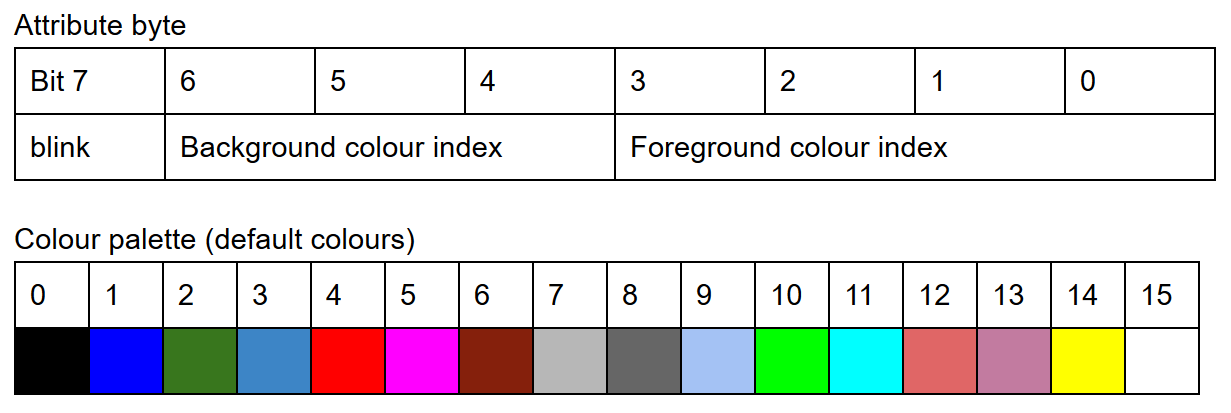
The attribute byte layout is the same as other text modes. A single blink bit, 3 bits of background colour and 4 bits of foreground. These could be interpreted in other ways (for example disabling blinking can allow for more background colours) but at the moment they simply index into one of 8 available background colours or 16 available foreground colours. I’ve fixed the colours themselves but there is no reason as to why these colours could not be memory mapped so that the palette can be changed programmatically.
 Blinking is achieved by checking an internal counter, along with the blink attribute bit. If the blink bit is set, and the counter is in a non-blink state, the background color is chosen regardless of the glyph properties.
text_gen states
entity text_gen is
  Port (
    I_clk_pixel : in  STD_LOGIC;
    I_clk_pixel10x : in  STD_LOGIC;

    -- Inputs from VGA signal generator
    -- defines the 'next pixel'
    I_blank : in  STD_LOGIC;
    I_x : in  STD_LOGIC_VECTOR (11 downto 0);
    I_y : in  STD_LOGIC_VECTOR (11 downto 0);

    -- Request data for a glyph row from FRAM
    O_FRAM_ADDR : out STD_LOGIC_VECTOR (15 downto 0);
    I_FRAM_DATA : in STD_LOGIC_VECTOR (15 downto 0);

    -- Request data from textual memory TRAM
    O_TRAM_ADDR : out STD_LOGIC_VECTOR (15 downto 0);
    I_TRAM_DATA : in STD_LOGIC_VECTOR (15 downto 0);

    -- The data for the relevant requested pixel
    O_R : out STD_LOGIC_VECTOR (7 downto 0);
    O_G : out STD_LOGIC_VECTOR (7 downto 0);
    O_B : out STD_LOGIC_VECTOR (7 downto 0)
  );
end text_gen;
I have the text generator currently running at 10x pixel clock. This is probably being too safe, and I could bring it down to 5x. I’ll have to check the timing constraints more thoroughly.
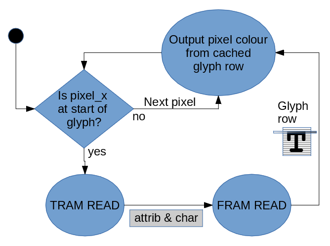
The module assumes the rows are scanned across the rows just like VGA. Each time a pixel X offset is input which we know is the start of a new glyph, a 2-byte TRAM fetch is initiated. The result of that fetch is used to latch colours from the attribute byte, and then fetch a 1-byte glyph row. That row is latched, and used by the next 8 pixels which are input to the generator. The states are short-circuited to the last stage.
I’ve attached full source of the module below.
Issues
 The first run of the text_gen module was actually very successful. I initialized the text block rams with some characters, and used a font ROM that I found which implemented an ASCII character set. The display worked, albeit with characters in the wrong place. The character I expected to be at position 0,0 was actually in 2,0.
I think there is an issue with timing in terms of how much latency the DSP48 slice needs to perform the multiplication required for calculating the TRAM location. One of the things that I needed to do from the previous part is that we need the next pixel locations to be used, rather than the current pixel which is what is used now. To get around this, I implemented a simple FIFO in the VGA signal generator.
The length of the FIFO can be changed, and the module now outputs a set of signals for the current pixel, which is sent to the TMDS encoders, as well as a set of prefetch signals, which are currently 8 pixels early. These prefetch signals are sent to the text_gen and allow for plenty of time for memory and other latencies to be accounted for. With this change, the output was correct. The expected character in 0,0 was rendered at that location.
Another issue was that the colour of any character was incorrect. For example, the character at position 2,0 had the colour of character 1,0. Moving around the point where the attribute byte and colours were latched in the state machine fixed this. I had been doing lots of asynchronous operations, but performing a latching operation on the RGB pixel data made it much more stable.
Testing out custom glyphs
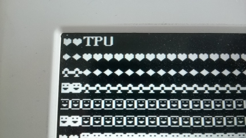
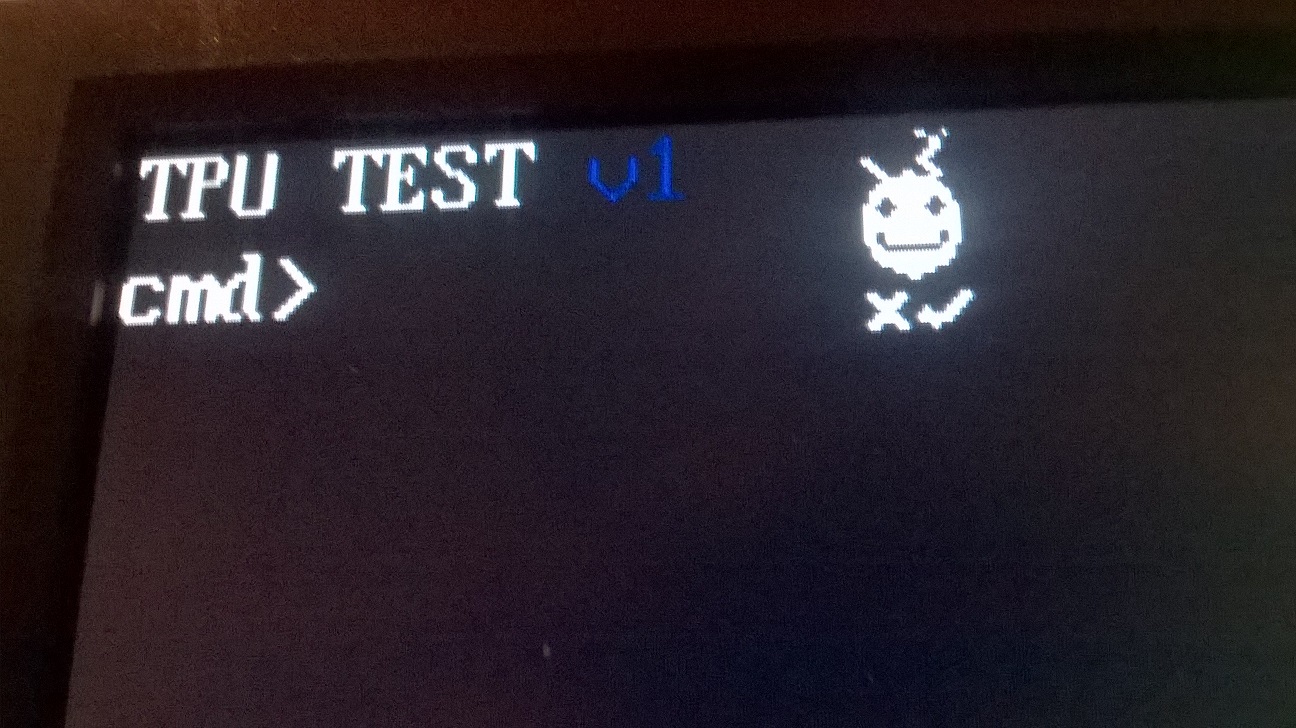
 One of the things I wanted was the ability to edit the font ram, and you can do that. Above you will see an image with some odd icon the the right, made up of 4 characters. I don’t really know what it is supposed to look like 🙂
Blinking in action
Wayhey. Time to write up the next part of the CPU in VHDL series 🙂 pic.twitter.com/C0bMcZA8vw
— Colin Riley (@domipheus) May 4, 2016
Wrap up
So text mode works, fairly well. This was a lot easier to get working than I thought it would. I hope to get a small demo together where input from the UART is echoed to this command prompt, and get some simple test commands working.
Thanks for reading, as always let me know your thoughts via twitter [@domipheus][11].
----------------------------------------------------------------------------------
-- Company: Domipheus Labs
-- Engineer: Colin Riley
--
-- Create Date:    16:27:52 05/01/2016
-- Design Name:    Text-mode output generator
-- Module Name:    text_gen - Behavioral
-- Project Name:
-- Target Devices: Tested on Spartan6
-- Tool versions:
-- Description:
--
--   For a 640x480 resolution set of input pixel locations an 80x25 text-mode
--   representation is generated. It is assumed the x direction pixels are
--   scanned linearly.
--
--   Glyphs are stored in a font ram as 16 bytes, each bit selecting a foreground
--   or background colour to display for a given pizel in an 8x16 glyph.
--
--   A clock faster than the pixel clock is needed to account for latency from
--   worse-case two dependant memory reads per pixel. It is adviced that pixel
--   locations are inputted early to the text_gen so data can be prefetched.
--
--
-- Dependencies:
--
-- Revision:
-- Revision 0.01 - File Created
-- Additional Comments:
--
----------------------------------------------------------------------------------
library IEEE;
use IEEE.STD_LOGIC_1164.ALL;
use IEEE.NUMERIC_STD.ALL;

entity text_gen is
   Port (
     I_clk_pixel : in  STD_LOGIC;
     I_clk_pixel10x : in  STD_LOGIC;

     -- Inputs from VGA signal generator
     -- defines the 'next pixel'
     I_blank : in  STD_LOGIC;
     I_x : in  STD_LOGIC_VECTOR (11 downto 0);
     I_y : in  STD_LOGIC_VECTOR (11 downto 0);

     -- Request data for a glyph row from FRAM
     O_FRAM_ADDR : out STD_LOGIC_VECTOR (15 downto 0);
     I_FRAM_DATA : in STD_LOGIC_VECTOR (15 downto 0);

     -- Request data from textual memory TRAM
     O_TRAM_ADDR : out STD_LOGIC_VECTOR (15 downto 0);
     I_TRAM_DATA : in STD_LOGIC_VECTOR (15 downto 0);

     -- The data for the relevant requested pixel
     O_R : out STD_LOGIC_VECTOR (7 downto 0);
     O_G : out STD_LOGIC_VECTOR (7 downto 0);
     O_B : out STD_LOGIC_VECTOR (7 downto 0)
     );
end text_gen;

architecture Behavioral of text_gen is
   -- state tracks the location in our state machine
   signal state: integer := 0;

   -- The blinking speed of characters is controlled by loctions
   -- in this counter
   signal blinker_count: unsigned(31 downto 0) := X"00000000";

   -- _us is the result of the address computation,
   -- whereas the logic_vector is the latched output to memory
   signal fram_addr_us: unsigned(15 downto 0):= X"0000";
   signal fram_addr: std_logic_vector( 15 downto 0) := X"0000";
   signal fram_data_latched: std_logic_vector(15 downto 0);

   -- Font ram addresses for glyphs above, text ram for ascii and
   -- attributes below.
   signal tram_addr_us: unsigned(15 downto 0):= X"0000";
   signal tram_addr: std_logic_vector( 15 downto 0) := X"0000";
   signal tram_data_latched: std_logic_vector(15 downto 0);

   -- the latched current_x value we are computing
   signal current_x: std_logic_vector( 11 downto 0) := X"FFF";

   -- Current fg and bg colours
   signal colour_fg: std_logic_vector(23 downto 0) := X"FFFFFF";
   signal colour_bg: std_logic_vector(23 downto 0) := X"FFFFFF";
   signal blink: std_logic := '1';

   -- outputs for our pixel colour
   signal r: std_logic_vector(7 downto 0) := X"00";
   signal g: std_logic_vector(7 downto 0) := X"00";
   signal b: std_logic_vector(7 downto 0) := X"00";

   type colour_rom_t is array (0 to 15) of std_logic_vector(23 downto 0);
   -- ROM definition
   constant colours: colour_rom_t:=(
   X"000000", -- 0 Black
   X"0000AA", -- 1 Blue
   X"00AA00", -- 2 Green
   X"00AAAA", -- 3 Cyan
   X"AA0000", -- 4 Red
   X"AA00AA", -- 5 Magenta
   X"AA5500", -- 6 Brown
   X"AAAAAA", -- 7 Light Gray
   X"555555", -- 8 Dark Gray
   X"5555FF", -- 9 Light Blue
   X"55FF55", -- a Light Green
   X"55FFFF", -- b Light Cyan
   X"FF5555", -- c Light Red
   X"FF55FF", -- d Light Magenta
   X"FFFF00", -- e Yellow
   X"FFFFFF"  -- f White
   );

begin


   tram_addr <= std_logic_vector(tram_addr_us);
   O_TRAM_ADDR <= tram_addr(14 downto 0) & '0';


   fram_addr <= std_logic_vector(fram_addr_us);
   O_FRAM_ADDR <= fram_addr(15 downto 0);

   process(I_clk_pixel)
   begin
      if rising_edge(I_clk_pixel) then
         blinker_count <= blinker_count + 1;
      end if;
   end process;

   process(I_clk_pixel10x)
   begin
      if rising_edge(I_clk_pixel10x) then
         if state < 8 then
            -- each clock either stay in a state, or move to the next one
            state <= state + 1;
         end if;

         if state = 3 then
            -- latch the data from TRAM and kick off FRAM read
            tram_data_latched <= I_TRAM_DATA;
            fram_addr_us <= (unsigned(tram_data_latched(7 downto 0)) * 16 ) + unsigned(I_y(3 downto 0));
            blink <= tram_data_latched(15);
            colour_fg <= colours( to_integer(unsigned( tram_data_latched(11 downto 8))));
            colour_bg <= colours( to_integer(unsigned( tram_data_latched(14 downto 12))));

         elsif state = 6 then
            -- latch the data from FRAM
            fram_data_latched <= I_FRAM_DATA;
            state <= 8;

         elsif current_x /= I_x then
            if (I_x(2 downto 0) = "000") then

               -- Each 8-byte pixel start, set the state and kick off TRAM fetch
               state <= 1;
               -- this multiply becomes a DSP slice
               tram_addr_us <= (unsigned( I_y(11 downto 4)) * 80) + unsigned(I_x(11 downto 3));
            else
               -- short circuit straight to shade state
               state <= 7;
            end if;
            current_x <= I_x;

         elsif state >= 8 then
            -- shade a pixel

            -- If the curret pixel should be foreground, and is not in a blink state, shade it foreground
            if (fram_data_latched(7 - to_integer(unsigned(I_x(2 downto 0)))) = '1')
               and (blinker_count(24) = '1' or (blink = '0')) then

              r <= colour_fg(23 downto 16);
              g <= colour_fg(15 downto 8);
              b <= colour_fg(7 downto 0);
            else
              r <= colour_bg(23 downto 16);
              g <= colour_bg(15 downto 8);
              b <= colour_bg(7 downto 0);
            end if;

         end if;

      end if;
   end process;

   -- When we are outside of our text area, have black pixels
   O_r <= r when unsigned(I_y) < 400 else X"00";
   O_g <= g when unsigned(I_y) < 400 else X"00";
   O_b <= b when unsigned(I_y) < 400 else X"00";

end Behavioral;
[5]: http://here http://www.xilinx.com/support/documentation/user_guides/ug389.pdf [6]: http://labs.domipheus.com/blog/wp-content/uploads/2016/05/dsp48a1.png [7]: http://labs.domipheus.com/blog/wp-content/uploads/2016/05/attribute_byte.png [8]: http://labs.domipheus.com/blog/wp-content/uploads/2016/05/text_mode_diagram.png [9]: http://labs.domipheus.com/blog/wp-content/uploads/2016/05/offset.jpg [10]: http://labs.domipheus.com/blog/wp-content/uploads/2016/05/customglyph.jpg [11]: http://twitter.com/domipheus